


This theorem is nothing but a combination of Thevenin’s Theorem and Norton’s Theorem. It is very useful theorem to find out voltage across the load and current through the load.This theorem is also called as PARALLEL GENERATOR THEOREM.
Millman’s theorem is applicable to a circuit which may contain only voltage sources in parallel or a mixture of voltage and current sources connected in parallel. Let’s discuss these one by one.
Circuit consisting only Voltage Sources
Let us have a circuit as shown in below figure a.
Here V1, V2 and V3 are voltages of respectively 1st, 2nd and 3rd branch and R1, R2 and R3 are their respective resistances. IL, RL and VT are load current, load resistance and terminal voltage respectively.
Now this complex circuit can be reduced easily to a single equivalent voltage source with a series resistance with the help of Millman’s Theorem as shown in figure b.
The value of equivalent voltage VE is specified as per Millman’s theorem will be –
This VE is nothing but Thevenin voltage and Thevenin resistance RTH can be determined as per convention by shorting the voltage source. So RTH will be obtained as
Now load current and terminal voltage can be easily found by
Let’s try to understand whole concept of Millman’s Theorem with the help of a example.
Example – 1
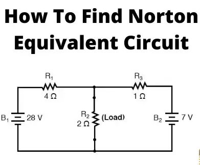
A circuit is given as shown in fig-c. Find out the voltage across 2 Ohm resistance and current through the 2 ohm resistance.
Answer : We can go through any solving method to solve this problem but the most effecting and time saving method will be none another than Millman’s theorem. Given circuit can be reduced to a circuit shown in fig-d where equivalent voltage VE can be obtained by millman’s theorem and that is
Equivalent resistance or Thevenin resistance can be found by shorting the voltage sources as shown in fig – e.
Now we can easily found the required current through 2 Ohm load resistance by Ohm’s law.
Voltage across load is,
Circuit is Consisting Mixture of Voltage and Current Source
Millman’s Theorem is also helpful to reduce a mixture of voltage and current source connected in parallel to a single equivalent voltage or current source. Let’s have a circuit as shown in below figure – f.
Here all letters are implying their conventional representation.This circuit can be reduced to a circuit as shown in figure – g.
Here VE which is nothing but thevenin voltage which will be obtained as per Millman’s theorem and that is
And RTH will be obtained by replacing current sources with open circuits and voltage sources with short circuits.
Now we can easily find out load current IL and terminal voltage VT by Ohm’s law.
Let’s have a example to understand this concept more properly.
Example 2 :
A circuit is given as shown in fig-h. Find out the current through load resistance where RL = 8 Ω.
Answer : This problem may seem to be difficult to solve and time consuming but it can easily be solved in a very less time with the help of Millman’s Theorem. The given circuit can be reduced in a circuit as shown in fig – i. Where, VE can be obtained with the help of Millman’s theorem,
Therefore, current through load resistance 8 Ω is,


What is Reciprocal Property?
In many electrical networks it is found that if the positions of voltage source and ammeter are interchanged, the reading of ammeter remains the same. It is not clear to you. Let’s explain it in details. Suppose a voltage source is connected to a passive network and an ammeter is connected to other part of the network to indicate the response.
Now any one interchanges the positions of ammeter and voltage source that means he or she connects the voltage source at the part of the network where the ammeter was connected and connects ammeter to that part of the network where the voltage source was connected.
The response of the ammeter means current through the ammeter would be the same in both the cases. This is where the property of reciprocity comes in the circuit. The particular circuit that has this reciprocal property, is called reciprocal circuit. This type of circuit perfectly obeys reciprocity theorem.
Explanation of Reciprocity Theorem
The voltage source and the ammeter used in this theorem must be ideal. That means the internal resistance of both the voltage source and ammetermust be zero. The reciprocal circuit may be a simple or complex network. But every complex reciprocal passive network can be simplified into a simple network. As per reciprocity theorem, in a linear passive network, supply voltage V and output current I are mutually transferable.
The ratio of V and I is called the transfer resistance. The theorem can easily be understood by this following example.

Concept of Compensation Theorem
This theorem is based on one basic concept. According to Ohm’s law, when current flows through any resistor, there would be a voltage drop across the resistor. This dropped voltage opposes the source voltage. Hence voltage drop across a resistance in any network can be assumed as a voltage source acting opposite to the source voltage. The compensation theorem depends upon this concept.
Explanation of Compensation Theorem
According to this theorem, any resistance in a network may be replaced by a voltage source that has zero internal resistance and a voltage equal to the voltage drop across the replace resistance due to the current which was flowing through it.
This imaginary voltage source is directed opposite to the voltage source of that replaced resistance. Think about a resistive branch of any complex network that’s value is R. Let’s assume current I is flowing through that resistor R and voltage drops due to this current across the resistor is V = I.R. According to compensation theorem, this resistor can be replaced by a voltage source that’s generated voltage will be V (= IR) and will be directed against the direction of network voltage or direction of current I.
Example of Compensation Theorem
The compensation theorem can easily be understood by this following example.
Here in the network for 16V source, all the currents flowing through the different resistive branches are shown in the first figure. The current through the right most branch in the figure is 2A and its resistance is 2 Ω. If this right most branch of the network is replaced by a voltage source directed as shown in the second figure, then current through the other branches of the network will remain the same as shown in the second figure.
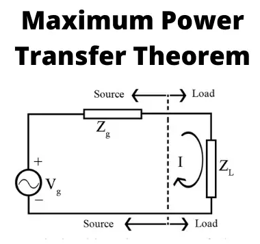

Maximum Power Transfer Theorem
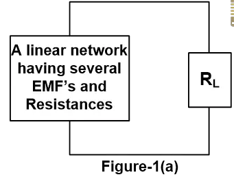
Suppose we have a voltage source or battery that’s internal resistance is Ri and a load resistance RL is connected across this battery. Maximum power transfer theorem determines the value of resistance RL for which, the maximum power will be transferred from source to it. Actually the maximum power, drawn from the source, depends upon the value of the load resistance. There may be some confusion let us clear it.
Power delivered to the load resistance,![]()
To find the maximum power, differentiate the above expression with respect to resistance RL and equate it to zero. Thus,![]()
Thus in this case, the maximum power will be transferred to the load when load resistance is just equal to internal resistance of the battery.
Maximum power transfer theorem can be applicable in complex network as follows-
A resistive load in a resistive network will abstract maximum power when the load resistance is equal to the resistance viewed by the load as it looks back to the network. Actually this is nothing but the resistance presented to the output terminals of the network. This is actually Thevenin equivalent resistance as we explained in Thevenin’s theorem if we consider the whole network as a voltage source. Similarly, if we consider the network as current source, this resistance will be Norton equivalent resistance as we explained in Norton theorem.
Video Representation of Maximum Power Transfer Theorem

This theorem has been introduced in the year of 1952 by Dutch Electrical Engineer Bernard D.H. Tellegen. This is a very useful theorem in network analysis. According to Tellegen theorem, the summation of instantaneous powers for the n number of branches in an electrical network is zero. Are you confused? Let’s explain. Suppose n number of branches in an electrical network have i1, i2, i3, …………. in respective instantaneous currents through them. These currents satisfy Kirchhoff’s Current Law.


Again, suppose these branches have instantaneous voltages across them are v1, v2, v3, ……….. vn respectively. If these voltages across these elements satisfy Kirchhoff Voltage Law then,
vk is the instantaneous voltage across the kth branch and ik is the instantaneous current flowing through this branch. Tellegen theorem is applicable to lumped networks that consist of linear, non-linear, time variant, time-invariant, and active and passive elements.
This theorem can easily be explained by the following example.
In the network shown, arbitrary reference directions have been selected for all of the branch currents, and the corresponding branch voltages have been indicated, with positive reference direction at the tail of the current arrow.
For this network, we will assume a set of branch voltages satisfy the Kirchhoff voltage law and a set of branch current satisfy Kirchhoff current law at each node.
We will then show that these arbitrary assumed voltages and currents satisfy the equation.
And it is the condition of Tellegen theorem.
In the network shown in the figure, let v1, v2 and v3 be 7, 2 and 3 volts respectively. Applying Kirchhoff Voltage Law around loop ABCDEA. We see that v4 = 2 volt is required. Around loop CDFC, v5 is required to be 3 volt and around loop DFED, v6 is required to be 2. We next apply Kirchhoff’s Current Law successively to nodes B, C and D.
At node B let ii = 5 A, then it is required that i2 = – 5 A. At node C let i3 = 3 A and then i5 is required to be – 8. At node D ssume i4 to be 4 then i6 is required to be – 9. Carrying out the operation of equation,
We get,
Hence Tellegen theorem is verified.
What is Norton’s Theorem And How to Find The Norton Equivalent Circuit (Examples Included)
What is Norton Theorem? (Norton’s Equivalent Circuit)
Norton’s Theorem (also known as the Mayer–Norton theorem) states that it is possible to simplify any linear circuit to an equivalent circuit with a single current source and equivalent parallel resistance connected to a load. The simplified circuit is known as the Norton Equivalent Circuit.
More formally, Norton’s theorem can be stated as:
“A circuit having any linear bilateral elements and active sources can be replaced by a simple two-terminal network consisting of an impedance and a current source, regardless of the complexity of the network.”
Norton theorem is a parallel to Thevenin’s theorem. And it is widely used in circuit analysis to simplify complex networks and to study the circuit’s initial condition and steady-state response.

As shown in the above figure, any complex bilateral network simplifies into a simple Norton equivalent circuit.
Norton equivalent circuit consists of an equivalent impedance connected parallel with a current source and load resistance.
The constant current source used in Norton equivalent circuit is known as Norton current IN or short circuit current ISC.
Norton theorem was derived by Hans Ferdinand Mayer and Edward Lawry Norton in 1926.
Norton Equivalent Formula
As shown in the Norton equivalent circuit, the Norton current is divided into two paths. One path passes through the equivalent resistance and the second path passes through the load resistance.
Therefore, the current passing through the load resistance can be derived by the current divider rule. And the formula for the Norton theorem is;
![\[ I_L = \frac{R_{EQ}}{R_L + R_{EQ}} \times I_N \]](https://www.electrical4u.com/wp-content/ql-cache/quicklatex.com-160c4f03ea064c70f6f2e62801225bbb_l3.png?ezimgfmt=rs:169x43/rscb38/ng:webp/ngcb38 "Rendered by QuickLaTeX.com")
How to Find Norton Equivalent Circuit
Any complex bilateral network is replaced by a simple Norton equivalent circuit. And it consists of;
- Norton equivalent resistance
- Norton equivalent current
- Load resistance
Norton Equivalent Resistance
Norton equivalent resistance is similar to the Thevenin equivalent resistance. To calculate the Norton equivalent resistance, we need to remove all active sources of the network.
But the condition is; all sources must be independent sources. If the network consists of dependent source/s, you need to use other methods to find Norton equivalent resistance.
In case, the network consists of only of independent sources, all sources are removed from the network by short-circuiting the voltage source and open-circuit the current source.
While calculating the Norton equivalent resistance, the load resistance is open-circuited. And find the open-circuit voltage between load terminals.
Sometimes, the Norton resistance is also known as Thevenin equivalent resistance or open-circuit resistance.
Let’s understand with an example.

First, check the network having any dependent sources? In this case, all sources are independent sources; 20V voltage source and 10A current source.
Now, remove both sources by the short-circuiting voltage source and open-circuit current source. And open load terminals. So, the network remains as below figure.

Now, find the open-circuit voltage by making series and parallel connections of resistances.
Resistances 6Ω and 4Ω are in series. So, the total resistance is 10Ω.


Both 10Ω resistances are in parallel. So, equivalent resistance REQ = 5Ω.
Norton Equivalent Current
To calculate the Norton equivalent current, the load resistance is short-circuited. And find current passing through the short-circuited branch.
So, Norton current or Norton equivalent current is also known as short-circuit current.
Norton Equivalent Resistance with Dependent Source
To calculate the Norton equivalent resistance for a circuit having a dependent source, we need to calculate the open-circuit voltage (VOC) across the load terminals.
Open-circuit voltage is similar to the Thevenin equivalent voltage.
Norton and Thevenin Equivalent Circuits
Norton equivalent circuit is a dual network of the Thevenin equivalent circuit. Norton and Thevenin theorem widely used to solve complex circuits in network analysis.
As we have seen, the Norton equivalent circuit consists of a Norton current source and Thevenin equivalent circuit consists of a Thevenin voltage source.
The equivalent resistance is the same in both cases. To convert Norton to Thevenin equivalent circuit, source transformation is used.
In the above example, the Norton current source and parallel equivalent resistance can be converted into a voltage source and resistance connected in series.


What is Thevenin’s Theorem (Thevenin Equivalent)?
Thevenin theorem (also known as the Helmholtz–Thévenin theorem) states that any linear circuit containing only voltage sources, current sources, and resistances can be replaced by an equivalent combination of a voltage source (VTh) in series with a single resistance (RTh) connected across the load. This simplified circuit is known as the Thevenin Equivalent Circuit.
Thevenin’s theorem was invented by a French engineer Léon Charles Thévenin (hence the name).
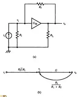
Thevenin theorem is used to convert a complex electrical circuit to a simple two-terminal Thevenin equivalent circuit. A Thevenin equivalent circuit contains one Thevenin resistance and Thevenin voltage source connected with a load, as shown in the figure below.

Thevenin resistance (Rth) is also known as equivalent resistance. And Thevenin voltage (Vth) is an open-circuit voltage across load terminals.
This theorem is suited with only linear circuits. If the circuit has elements like semiconductor components or gas-discharging components, you can not apply Thevenin’s Theorem
Thevenin Equivalent Formula
Thevenin equivalent circuit contains an equivalent voltage source, equivalent resistance, and load as shown in above figure-1(b).
Thevenin equivalent circuit has a single loop. If we apply a KVL (Kirchhoff’s Voltage Law) to this loop, we can find the current passing through the load.
According to the KVL,
![\[ V_{th} = I ( R_{th} + R_L ) \]](https://www.electrical4u.com/wp-content/ql-cache/quicklatex.com-079f3d5f3f64b098df671df768059345_l3.png?ezimgfmt=rs:143x19/rscb38/ng:webp/ngcb38 "Rendered by QuickLaTeX.com")
![\[ I = \frac{V_{th}}{( R_{th} + R_L)} \]](https://www.electrical4u.com/wp-content/ql-cache/quicklatex.com-f71cc16372390f917304b40506ab8e71_l3.png?ezimgfmt=rs:122x42/rscb38/ng:webp/ngcb38 "Rendered by QuickLaTeX.com")
How to Find The Thevenin Equivalent Circuit
The Thevenin equivalent circuit contains Thevenin resistance and Thevenin voltage source. therefore, we have to find these two values for Thevenin equivalent circuit.
Thevenin Equivalent Resistance
To calculate the Thevenin equivalent resistance, remove all power sources from the original circuit. And voltage sources are short-circuited and current sources are opened.
Hence, the remaining circuit has only resistances. Now, calculate the total resistance between the open connection points across load terminals.
The equivalent resistance is calculated by making series and parallel connection of resistances. And find a value of equivalent resistance. This resistance is also known as Thevenin resistance (Rth).
Thevenin Equivalent Voltage
To calculate the Thevenin equivalent voltage, the load impedance is open-circuited. And find an open-circuit voltage across the load terminals.
Thevenin equivalent voltage (Veq) is equal to the open-circuit voltage measured across two terminals of load. This value of the ideal voltage source is used in Thevenin equivalent circuit.
Thevenin Equivalent Dependent Source
If a circuit network consists of some dependent sources, the Thevenin resistance is calculated by a different method. In this condition, the dependent sources kept as it is. You cannot remove (open or short circuit) the voltage or current sources.
There are two methods to find Thevenin resistance in the case of dependent sources.
Method 1
In this method, we have to find Thevenin voltage (Vth) and short-circuit current (Isc). Put these values in the below equation to find the Thevenin resistance.
![\[ R_{th} = \frac{V_{th}}{I_{sc}} \]](https://www.electrical4u.com/wp-content/ql-cache/quicklatex.com-dedf361c21339a671d70009e82f191ac_l3.png?ezimgfmt=rs:78x39/rscb38/ng:webp/ngcb38 "Rendered by QuickLaTeX.com")

Thevenin voltage is same as the voltage across the terminals A and B. And we have the value of Thevenin voltage. Short-circuit current is obtained by shorting load terminals and find a current that passes through the shorted branch.


As name implies, the main concept of this theorem which is based upon substitution of one element by another equivalent element. Substitution theorem gives us some special insights in circuit behavior. This theorem is also used to prove several other theorems.
Statement of Substitution Theorem
Substitution theorem states that if an element in a network is replaced by a voltage source whose voltage at any instant of time is equals to the voltage across the element in the previous network then the initial condition in the rest of the network will be unaltered or alternately if an element in a network is replaced by a current source whose current at any instant of time is equal to the current through the element in the previous network then the initial condition in the rest of the network will be unaltered.
Explanation of Substitution Theorem
Let us take a circuit as shown in fig – a,

Let, V is supplied voltage and Z1, Z2 and Z3 is different circuit impedances. V1, V2 and V3 are the voltages across Z1, Z2 and Z3 impedance respectively and I is the supplied current whose I1 part is flowing through the Z1 impedance whereas I2 part is flowing through the Z2 and Z3 impedance.
Now if we replace Z3 impedance with V3 voltage source as shown in fig-b or with I2 current source as shown in fig-c then according to Substitution Theorem all initial condition through other impedances and source will remain unchanged.
i.e. – current through source will be I, voltage across Z1 impedance will be V1, current through Z2 will be I2 etc.
Example of Substitution Theorem
For more efficient and clear understanding let us go through a simple practical example:
Let us take a circuit as shown in fig – d.
As per voltage division rule voltage across 3Ω and 2Ω resistance are
If we replace the 3Ω resistance with a voltage source of 6 V as shown in fig – e, then
According to Ohm’s law the voltage across 2Ω resistance and current through the circuit is
Alternately if we replace 3Ω resistance with a current source of 2A as shown in fig – f, then
Voltage across 2Ω is V2Ω = 10 – 3× 2 = 4 V and voltage across 2A current source is V2A = 10 – 4 = 6 V
We can see the voltage across 2Ω resistance and current through the circuit is unaltered i.e all initial condition of the circuit is intact.

